
For some GWR modellers, one of the appeals is the propensity of Swindon’s designers to hide all the complex rotating and reciprocating rods between the frames, making them almost invisible. However, from certain angles, most if not all of these are visible. Most notably, the valve chest rod can only really be driven by the inside motion, and this sits outside the frames, in the case of two cylinder locomotives like the Hall discussed here, it is above the cylinder, the four cylinder locos have a rocker arm system coming out of the front of the cylinder and passing between the frames well in front.
Perhaps I have persuaded you to go around adding inside motion to your fleet of GWR locos, perhaps not. Either way, I decided to fit it when building my Hall. This was, to some extent, because provision was made for it in the Martin Finney kit I was building, and a kit for the inside motion was available. The motion I built was modified Stephenson link motion, and with the Hall being outside cylindered, no crank axle was required, only a pair of eccentric cranks, which are friction fitted onto the axle, although I will apply some thread retainer after painting. The lack of a crank axle makes the build much easier, as there is no need to silver solder the crank axle.
The first, and in my opinion, most important step, is to fully understand how the motion works, it will be virtually impossible to build unless you understand what is moving, in which direction, and equally importantly, what is fixed. This last point may seem obvious, but without direct connection to crosshead, or a fixing on the crankpin, it is less obvious on inside motion. Also, there is virtually no footage of inside motion running on prototypes, as nobody’s ever bothered to put a camera down there! The motion is running fixed in mid gear, as is customary for 4mm models.
Once we understand how this works, the inside motion can be built in a very similar way to outside motion. I used the chemical blackening method and brass lace pins to join the components together. Simply chemically blacken the area around the hole of one of the components, insert the lace pine through the components, with the blackened component next to the pin head, then solder the rear component to the lace pin, trim and file flush. You should be left with a free moving joint, with very little slop or play.
I found that following the sequence laid out in the instructions worked well for me, and these are available on the Brassmasters website, so I won’t bore you by repeating them here. However, it is important to consider when building the rest of the chassis how you will support the motion and how, in the case of outside cylindered, inside motion locomotives, how the motion is transmitted through or over the frames. I found that one of the last things I did was to assemble the eccentrics, and this merits a little further discussion.
 The running of the assembly can be tested without them in place, and the ‘sandwich’ assembly of the eccentric cranks is done with the eccentric rods in place, these rods are retained by soldering the two eccentric cranks together, alignment is achieved using the axle hole and a small secondary hole for a fixing stud.
In my case the motion is suspended from a pivot point at the front, the middle of the three driving axles, and the reverser rod. Fitting the motion is a little fiddly, you don’t want slop on any of the fixing points, especially the axle, so threading the motion sets onto the axle, between OO gauge frames with fixed bearings was a little tricky, springing, or working to a more prototypical gauge will make this much easier.
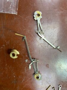
I’ve included a few pictures of the completed motion sets, currently resting outside of the frames awaiting the painting of the loco. Also, I’ve included a video of just one of the motion sets temporarily fitted(note the copious use of blu-tac) and running within the frames under human power.